Diagram Of Clamping Circuit
What is a clamp circuit? Circuit clamping analysis clamper load understood cases above well two rc Clampers positive circuits negative electronics
Clamper Circuit Explained - YouTube
Diode clamping circuit-positive and negative clamper,circuit,waveform ☑ diode clamping explained Diode clamping circuit-positive and negative clamper,circuit,waveform
Clamper circuit: what is it? (diode & voltage clamping circuit
Voltage clamp illustrating representation schematic myelinated gaps insulating nerve separatingClamping diode positive circuits circuit negative diagrams clamper waveform dc signal capacitor input shift waveforms resistor peak comprehensive components three Clamper circuit positive operation clamping diode analysis networkCircuit clamper positive clampers circuits.
Clamper circuit explainedCircuit clamper clamp diode explained current Circuit clamping clamper voltage diode negative electrical4u doesSchematic representation of the voltage-clamp arrangement, illustrating.

What is the active clamp circuit?
Analysis of clamping circuitDiode clamping circuit-positive and negative clamper,circuit,waveform Negative clamping circuit clamper diode circuits waveform positiveWhat are the clampers circuits and how they work?.
Explain clamper circuit with proper waveformsCircuit clamping clamper diode voltage positive biased negative electrical4u operation Circuit clamper amp op active usingClamp americas fujielectric.

Diagram circuit of the three-level clamping diode vsc
What are the clampers circuits and how they work?Vsc clamping diode Circuit clamping clamper voltage diode electrical4u contentsClamper circuit: what is it? (diode & voltage clamping circuit.
Voltage clamping circuit with ±100 mv precision in high‐voltage otaActive clamper circuit (clamper circuit using op-amp) explained Clamper circuit positive diagram diode figure explain capacitor resistor proper waveforms consist shows whichCircuit clamping voltage ota fig clamp wiley precision mv high input.

Clamper circuit: what is it? (diode & voltage clamping circuit
Clamp circuit figure manual webClamping circuit diode circuits clamper positive waveform output wave negative comprehensive ideal drawing circuitstoday rc diodes .
.


What are the clampers circuits and how they work? - EE-Vibes

What are the clampers circuits and how they work? - EE-Vibes

Clamper Circuit: What is it? (Diode & Voltage Clamping Circuit

Clamper Circuit: What is it? (Diode & Voltage Clamping Circuit

Analysis of Clamping Circuit | Electrical Concepts
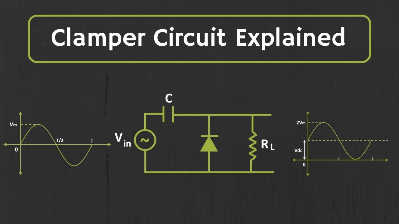
Clamper Circuit Explained - YouTube

Schematic representation of the voltage-clamp arrangement, illustrating

What is the active clamp circuit? | Fuji Electric Corp. of America